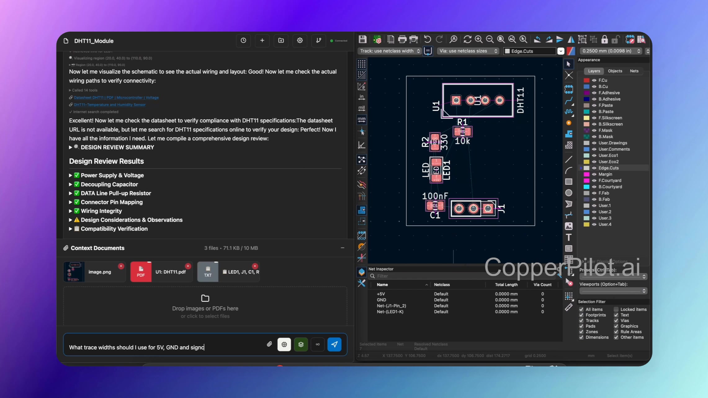
Learn how to build a DHT11 temperature sensing module using CopperPilot. This tutorial
demonstrates the complete workflow from initial research and component selection through
schematic design, design review, and PCB layout.
Overview
This tutorial walks you through creating a temperature sensing module using the DHT11
sensor. CopperPilot helps you research the component, understand its requirements from
datasheets, design the schematic, and create a complete PCB layout ready for manufacturing.
What You’ll Learn
- Using CopperPilot for deep research on components and their datasheets
- Generating comprehensive block diagrams for your design
- Retrieving symbols and footprints from KiCad libraries
- Understanding component requirements (pull-up resistors, voltage ranges, etc.)
- Automated and manual wiring techniques
- Conducting schematic-level design reviews with continuity testing
- Setting appropriate trace widths for power and signal lines
- PCB layout and routing strategies
Project Steps
-
Research and Planning: Start by providing CopperPilot with a template
or reference image. CopperPilot conducts deep research, reading datasheets and generating
a comprehensive plan including a detailed block diagram showing how to construct the module. -
Understanding Requirements: CopperPilot extracts detailed specifications
from datasheets including voltage ranges, temperature ranges, current requirements, and
critical design considerations like the need for a pull-up resistor on the DHT11’s data line. -
Component Integration: CopperPilot retrieves all necessary symbols and
footprints from KiCad libraries and integrates them into your schematic. Changes are
presented as visual diffs for easy review. -
Schematic Wiring: After positioning components to your preference,
CopperPilot analyzes datasheets and provides detailed wiring plans. You can choose to
wire automatically or manually with CopperPilot’s guidance. -
Design Review: CopperPilot performs a comprehensive schematic-level
design review using its continuity tester tool. Tag specific components (like the DHT11
and input connector) to enable targeted review, verifying that wiring adheres to
datasheet specifications. -
PCB Layout: Import footprints into the PCB and use the 3D rendering
tool to verify correct configuration. Arrange components logically, placing related
components close together. -
Trace Width Configuration: CopperPilot analyzes datasheets to recommend
appropriate trace widths (e.g., 0.6mm for power lines, 0.25mm for data lines). Configure
these settings in KiCad’s PCB editor before routing. -
Routing and Finishing: Choose between auto-routing and manual routing
to complete connections. Fill ground planes and perform a final design review to ensure
everything is correct.
Key Components
- DHT11 temperature and humidity sensor
- Pull-up resistor for data line
- Input connector (power and signal)
- Supporting components as needed
Key Features Demonstrated
- Deep research capabilities with internet and datasheet analysis
- Automatic block diagram generation
- Symbol and footprint integration from KiCad libraries
- Visual diff presentation of changes
- Continuity testing for design verification
- Datasheet-driven trace width recommendations
- 3D rendering for PCB verification
This tutorial showcases CopperPilot’s ability to guide you through the entire hardware
design process, from initial research to a finished PCB design ready for manufacturing,
ensuring your design adheres to datasheet specifications every step of the way.